Loading…
Micro-Wind Systems · DAWT architecture
Wind energy, protected by design.
Coevo's Micro-Wind system is being developed as a compact, enclosed wind charging platform for battery-backed remote infrastructure. The system uses a DAWT-style architecture, or Diffuser-Augmented Wind Turbine, intended to improve wind capture in a compact form factor while supporting safer, more practical deployment around remote industrial assets.
Purpose
Power that shows up when nothing else can.
Solar owns the daytime. This platform owns everything else — nights, storms, winter, dust, and shade. Paired with solar and storage, it keeps field batteries at a healthier state of charge around the clock, which is where battery life, uptime, and operating cost are actually won.
Reduced deep cycling
Trickle charging
Extended battery life
Improved uptime
Reduced truck rolls
Fewer battery replacements
Solar complementarity
Enclosed rotor
Modular service
Configurable environmental protection
Benefits are design intents subject to site conditions and validation through testing and pilot deployments.
Diffuser-Augmented Wind Turbine
What DAWT means, in plain terms.
DAWT stands for Diffuser-Augmented Wind Turbine. Coevo's Micro-Wind system uses a DAWT-style architecture intended to improve wind capture in a compact, enclosed form factor for remote infrastructure and battery-backed field assets.
Coevo's Micro-Wind architecture is designed to use a compact diffuser and enclosure approach to support wind capture in remote, industrial, and infrastructure-based environments. The rotor is an enclosed-blade vertical-axis design, and the surrounding shroud has been engineered with an integrated diffuser intended to improve blade protection and low-wind performance. Aerodynamic gains are design intent and remain subject to wind-tunnel validation.
What the architecture is intended to do
- Improve wind capture in a compact form factor
- Protect the blades behind a structural enclosure
- Support low-wind performance at typical field sites
- Accept wind from any horizontal direction, without yaw
- Enable deployment where open blades are restricted
Aerodynamic performance gains from the diffuser are design intent and remain subject to wind-tunnel validation.
System anatomy
Every component, engineered for the field.
Select a component to see its role in the platform. The diagram is a high-level engineering concept — detailed internals remain confidential.
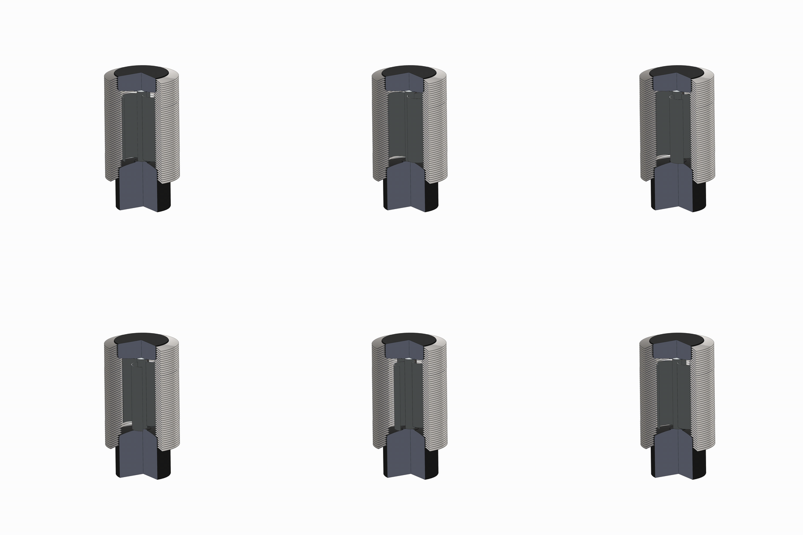
Engineering concept animation
Rotor
The enclosed vertical-axis rotor — the spinning element visible in the animation.
Product family
Four preliminary configurations. One shared platform.
Larger models are physically larger — swept area, rotor dimensions, and estimated output scale together. Compare up to three models below.
MW-20
MW20
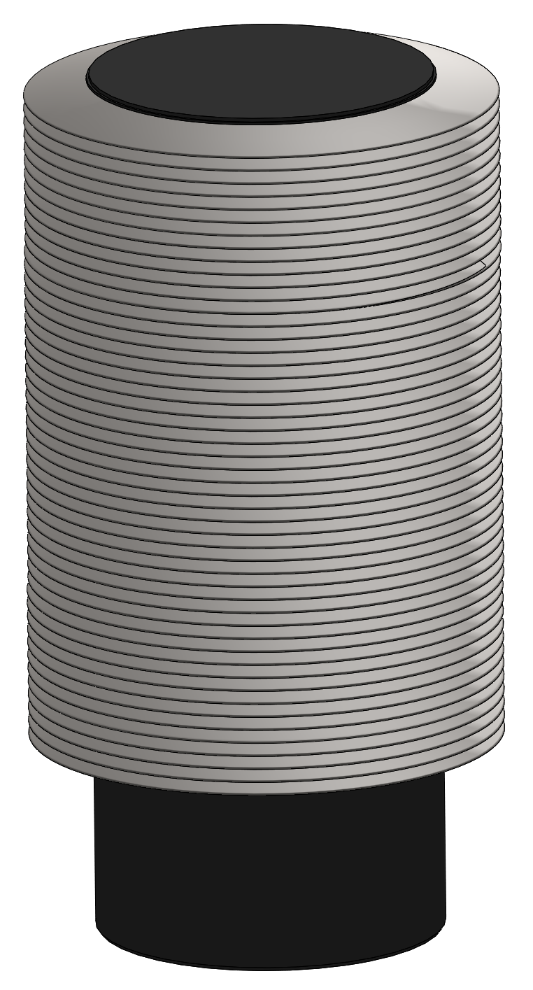
- Swept area
- 0.2 m²
- Est. @ 7 m/s
- 8.4–10.5 W
- Rotor Ø × H
- 0.37 × 0.55 m
Compact sensor and telemetry support
MW-50
MW50
- Swept area
- 0.5 m²
- Est. @ 7 m/s
- 21–26.3 W
- Rotor Ø × H
- 0.58 × 0.87 m
Remote infrastructure and battery support
MW-125
MW125
- Swept area
- 1.25 m²
- Est. @ 7 m/s
- 52.5–65.7 W
- Rotor Ø × H
- 0.91 × 1.37 m
Multi-load field compounds
MW-275
MW275
- Swept area
- 2.75 m²
- Est. @ 7 m/s
- 115.5–144.4 W
- Rotor Ø × H
- 1.35 × 2.03 m
Infrastructure and auxiliary power
Preliminary engineering configuration. Final dimensions, ratings, generator selection, enclosure design, and operating limits are subject to validation.
Designed to support
The equipment that keeps infrastructure running.
Filter by category to explore the load classes the platform is being developed to support.
- SCADA and RTU systems
- Pipeline telemetry
- Tank monitoring
- Metering stations
- Flow meters
- Industrial controls
- Weather stations
- Environmental monitoring stations
- Agricultural sensors
- Utility telemetry
- Transportation sensors
- Rail monitoring
- Bridge monitoring
- Marine navigation aids
- Security systems
- Remote alarms
- Smart infrastructure
- Low-power communications
- IoT gateways
- Field communications
- Emergency field systems
- Defense-related field systems
Environmental configurations
Configured for the site, not the showroom.
Standard
Baseline configuration for temperate, non-classified sites.
Wet and coastal
Corrosion-resistant materials and drainage targets.
Dust and industrial
Ingress-focused screening and filtration targets.
Cold-weather
Icing detection, drainage, and low-temperature operation targets.
High-altitude
Density-adjusted performance modeling and thermal targets.
Storm-prone
Elevated survival-load and shutdown-behavior targets.
Marine
Salt-spray exposure and marine-grade material targets.
Classified-location development configuration
Development track toward classified-area assessment of the complete assembly.
Environmental protection targets and available configurations will depend on final product design and certification.
Battery support
Shallower cycles. Healthier batteries.
The conceptual comparison shows how supplemental wind input may reduce depth of discharge versus battery-only and solar-plus-battery systems — lifting the overnight floor that drives battery wear.
Illustrative modeling only. Battery life depends on chemistry, temperature, cycling, charge control, load, maintenance, and operating conditions — no battery-life percentage is guaranteed.
Battery-support contribution
% state of charge · illustrativeConceptual 72-hour comparison of battery-only, solar + battery, and solar + battery + wind. Illustrative only — not a battery-life guarantee.
Simulator
Model your wind, your model, your site.
Interactive concept visualization
SYSTEM STATUSSIMULATIONWIND SPEED5.4 m/sROTOR SPEED160 RPMEST. OUTPUT8.1 W
Simulation controls
Generating0 m/s12.1 mph25 m/s
kg/m³
Interactive concept visualization. Performance values are modeled estimates and will be updated following product validation.
Wind
5.4 m/s
12.1 mph
Rotor
160 RPM
Modeled, illustrative
Gross aero
10.6 W
Cp 0.22
Est. electrical
8.1 W
1 × MW-50
Daily
194 Wh
5.9 kWh/mo
Annualized
71 kWh
Steady-wind basis
Swept area
0.5 m²
5.38 ft²
Air density
1.225
kg/m³
Elec. efficiency
80%
Availability 95%
Battery support
16%
of a 1.2 kWh/day station · modeled
Data confidence: modeled engineering estimate — pending validation testing
Live estimated output
W · modeledWind speed over time
m/sEstimated power curve — MW-50
W vs m/sCp 0.20–0.25 band with illustrative cut-in, rated plateau, and cut-out shaping. Not a tested power curve.
Daily energy estimate by model
Wh/dayAt a steady 5.4 m/s × 1 unit. Steady-wind assumption overstates real sites; see assumptions.
Battery-support contribution
% state of charge · illustrativeConceptual 72-hour comparison of battery-only, solar + battery, and solar + battery + wind. Illustrative only — not a battery-life guarantee.
Cumulative generated energy
Wh · this sessionAerodynamic analysis
Where the air actually goes.
CFD analysis lets the program evaluate rotor geometry, diffuser and shroud interaction, and wake behavior in simulation — resolving design questions long before a prototype is cut. These are results from a development rotor at a low-wind operating point.
CFD · Aerodynamic analysisVane B · 80 RPM · 2.68 m/s (6 mph)
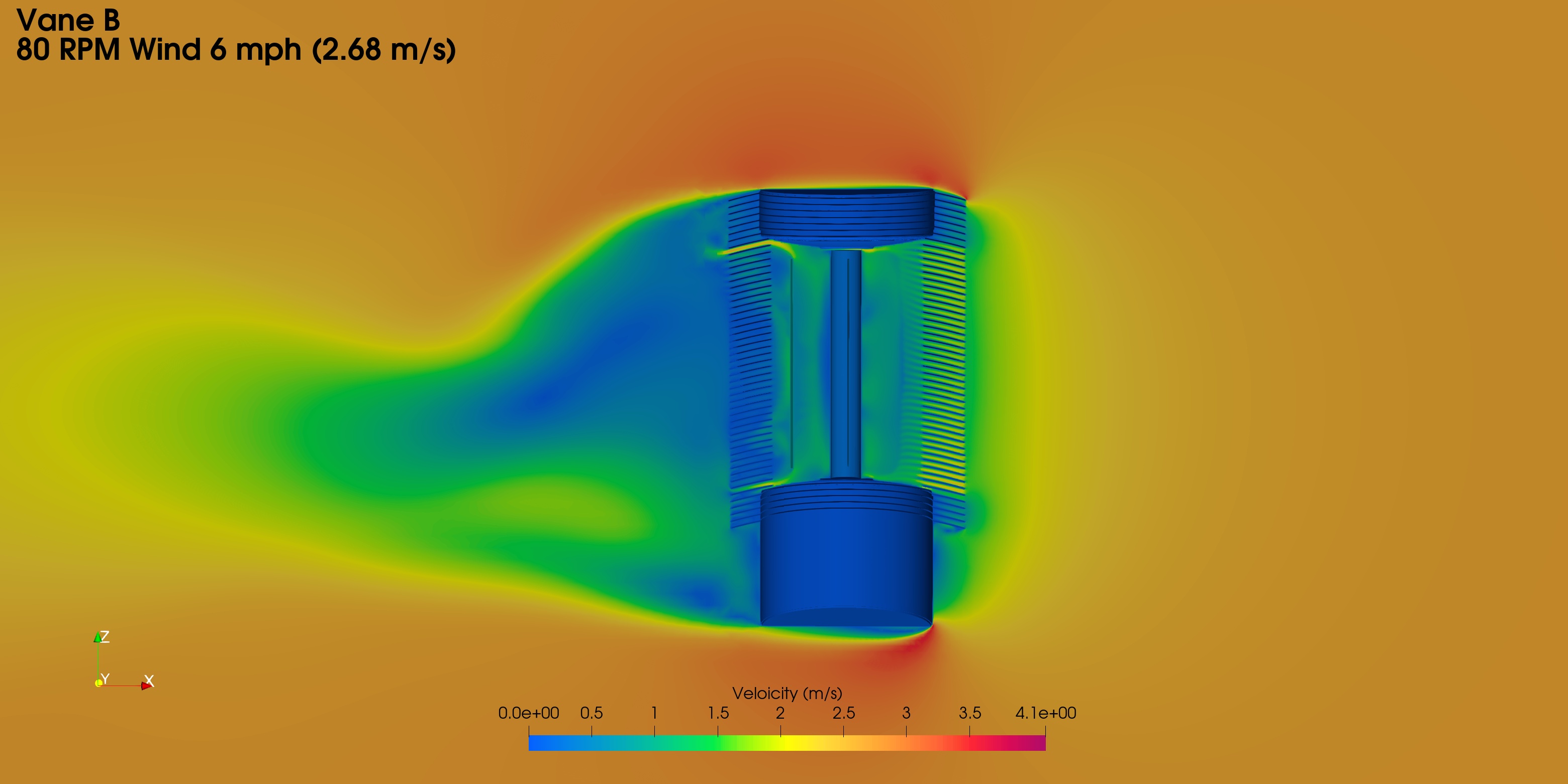
Velocity field — elevation section
A vertical slice through the complete assembly. Air enters through the louvered shroud, works on the rotor, and exits downstream — while the housings above and below sit in near-still air.
How to read it
Shows how the protective enclosure shapes flow into and out of the rotor.
Preliminary CFD analysis of a development rotor configuration at a single operating point. Simulation results inform design direction — they are not a substitute for instrumented power-curve testing, and no performance rating is derived from them here.
Engineering development
Built with teams that do this for a living.
Coevo develops the platform with two specialist engineering partners, each engaged where their strengths matter most — one carrying the design from simulation through fabrication, the other putting the results in a wind tunnel.
Design & build
A multi-disciplinary engineering development group
Carries a design from simulation through fabrication under one roof — the reason the program can ask a hard question and have hardware answering it the same month. The velocity fields and streamlines above are output from their work.
- Aerodynamic analysis and CFD simulation
- Mechanical design with structural and load-path analysis
- Rapid prototyping, machining, and in-house fabrication
- Design for manufacturing and production readiness
- Generator, power-conversion, and controls integration
Test & validate
An aerodynamics specialist with wind-tunnel facilities
Deep heritage in wind and flight systems, engaged to build test articles and characterize what the hardware actually does under controlled, repeatable conditions — the step that turns a simulated result into a measured one.
- Wind-tunnel testing across controlled wind speeds
- Applied aerodynamic design and analysis
- Prototype and test-article fabrication
- Performance characterization and data capture
- Independent validation of simulated results
Why we split the work
Enclosed micro-wind is a harder problem than an open rotor: the shroud, rotor, bearings, generator, and containment all interact, and every change to one moves the others. Simulation narrows that design space quickly and cheaply — but a wind tunnel is what tells you which parts of the model were right. Keeping the two in separate hands means our aerodynamic results get checked by a team that didn't produce the model.
Safety begins with controlling the moving system.
Surrounding the rotor with a protective structure is what lets Coevo pursue sites where exposed rotating machinery is unsuitable or restricted. These are engineering intents — each one subject to validation of the complete assembly.
- Reduced direct access to rotating blades
- Potential containment of damaged rotor components
- Reduced wildlife contact exposure
- Reduced risk from exposed rotating machinery
- Potential reduction of conventional blade-throw concerns
- Better fit for compact sites
- Greater control over ingress
- Application-specific screening options
- Cold-weather mitigation opportunities
- Protection of internal components
What enclosure does not automatically establish
Equipment qualification is based on identifying and mitigating risk pathways — including ignition pathways in classified locations — across the complete assembly. Enclosure is a prerequisite, not a certification conclusion.
Enclosure alone does not establish ATEX certification.
Enclosure alone does not establish IECEx certification.
Enclosure alone does not establish NEC suitability.
Enclosure alone does not certify a machine as OSHA compliant.
Enclosure alone does not guarantee wildlife approval.
Enclosure alone does not prove ice containment.
Enclosure alone does not prove blade-fragment containment.
The complete assembly requires assessment.
Site suitability remains jurisdiction- and application-dependent.
Physical access and guarding
Opening size and rotor standoff must be engineered together — there is no single universal “safe opening” dimension. Small openings may prevent finger or hand access; larger slots require greater standoff; very large openings may be treated as full-body access. Mounting height changes the applicable guarding considerations, and OSHA guarding duties and ISO reach-distance standards must be considered together, particularly for rotating systems mounted at or below seven feet.
Wildlife
Wildlife risk varies by site and species, and no single opening size establishes universal compliance. Screening may reduce access, but site assessment remains necessary. Some bats may pass through openings around 3/8 inch, and for birds the governing dimension is body cross-section rather than wingspan. Enclosure may materially reduce direct rotor exposure — it does not guarantee wildlife approval.
Ice and cold weather
Enclosure may reduce external blade-icing exposure, but inlets and outlets remain open for airflow and internal ice can still accumulate. Detection, shutdown behavior, anti-icing measures, drainage, and containment may all be needed depending on climate. Cold-weather design remains under engineering review.